.png?width=158&height=34&name=Autarco%20logo%20(1).png)
To access the Digital O&M page in Helios, simply navigate:
Main page for PV system → Asset Management → Digital O&M
This article walks you through every setting available on the Digital O&M page. For each setting you’ll find:
-
a short, plain-language explanation of what it does,
-
which inverter types it applies to, and
-
practical notes or tips for commissioning and troubleshooting.
Status
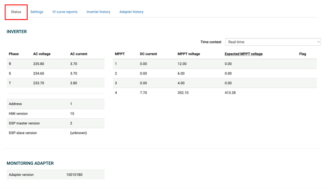
Within the Status tab, you can view key information such as voltages, currents, device addresses, and firmware versions for the selected inverter and its connected monitoring stick. With the latest update, this data is now displayed separately, making it easier to distinguish between inverter-specific and monitoring stick-specific details.
Settings
In the Settings tab, you’ll find several sub-tabs that let you explore and adjust various configurations, depending on the specific model installed in the system.
The available settings may differ based on whether you’re working with an On-Grid or Hybrid inverter. Even within the same category, certain models can have unique configuration options—so the exact menus and parameters you see might vary.
Hybrid inverter:

Grid inverter:

Datetime
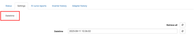
In this tab, you can view and set the inverter’s internal date and time.
Use the calendar to select the desired date. Click the clock icon to manually set the time, or use the left icon to automatically apply the current date and time. Once your settings are ready, click Apply to save them.
Keeping the time accurate is essential, especially for Hybrid inverters, to ensure precise Grid Trading schedules (Time of Use mode), allowing the system to charge your battery at the optimal times.
Grid
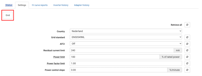
Select the desired Country and corresponding Grid Standard. If you need to adjust specific parameters related to that standard, you can do so in Advanced Grid Settings.
AFCI
Autarco inverters include a built-in Arc Fault Circuit Interruption (AFCI) feature, which detects arc faults in the DC circuit and automatically shuts down the inverter to prevent potential fire hazards. You can activate or configure the AFCI function directly in Digital O&M.
Residual current limit
Sets the threshold for continuous leakage current monitoring. Can be adjusted to align with local electrical safety standards.
Power limit
This setting restricts the inverter’s maximum AC power output to a percentage of its rated capacity. You can choose a fixed limit, for example, if your system is oversized and your grid connection can’t support the inverter’s full output. Alternatively, you can enable power limiting based on consumption using PELD (internal or external), which dynamically adjusts the power limit according to your energy use.
Power factor limit
Setting the power factor on an inverter controls how much reactive power it produces or absorbs, allowing you to balance efficiency, load correction, and grid support.
DRM Switch (only for On-Grid inverters)
Enables control via Demand Response Mode signals.
Power control slope (only for Hybrid inverters)
Defines the speed at which the inverter adjusts its power output when a change in power control percentage is commanded. A lower value results in a faster response, with a setting of zero allowing maximum adjustment speed.
Advanced Grid Settings
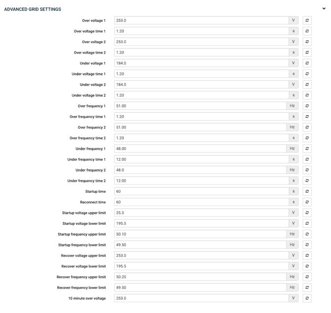
Over-grid Voltage Settings
-
Over voltage 1 (Intermediate Trip Limit - V1)
Voltage threshold at which the inverter will trip if exceeded for longer than the configured trip time. (Range: not greater than 276) -
Over voltage time 1 (Intermediate Trip Time - V1)
The maximum duration the voltage can remain above the intermediate limit before the inverter disconnects from the grid. (Range: not greater than 100) -
Over voltage 2 (Absolute Trip Limit - V2)
The maximum voltage the inverter will tolerate. If reached, the inverter will trip almost immediately to protect the system. (Range: not greater than 299) -
Over voltage time 2 (Absolute Trip Time - V2)
The time delay allowed once the absolute voltage limit is exceeded before the inverter trips. (Range: not greater than 5)
Under-grid Voltage Settings
-
Under voltage 1 (Intermediate Limit - V1)
Lower voltage threshold at which the inverter will trip if the voltage remains below this level for the configured time. (Range: not greater than 230) -
Under voltage time 1 (Intermediate Trip Time - V1)
Duration the voltage can stay below the intermediate limit before tripping occurs. (Range: not greater than 100) -
Under voltage 1 (Absolute Limit - V2)
Minimum voltage the inverter can tolerate. Falling below this will cause an almost immediate trip. (Range: not greater than 230) -
Under voltage time 2 (Absolute Trip Time - V2)
The time delay allowed once the absolute under-voltage limit is reached before the inverter disconnects. (Range: not greater than 5)
Over-grid Frequency Settings
-
Over frequency 1 (Intermediate Setting)
Frequency threshold above which the inverter will trip if sustained beyond the set trip time. (Range: not greater than 55) -
Over frequency time 1 (Intermediate Trip Time)
Duration the frequency can remain above the intermediate limit before tripping. (Range: not greater than 100) -
Over frequency 2 (Absolute Limit)
Maximum frequency tolerated before the inverter trips instantly or within the set delay. (Range: not greater than 50) -
Over frequency time 2 (Absolute Trip Time)
Time delay before tripping once the absolute over-frequency limit is exceeded. (Range: not greater than 5)
Under-grid Frequency Settings
-
Under frequency 1 (Intermediate Setting)
Frequency threshold below which the inverter will trip if it stays under the limit for the configured time. (Range: not greater than 50) -
Under frequency time 1 (Intermediate Trip Time)
Duration the frequency can remain below the intermediate limit before disconnection. (Range: not greater than 100) -
Under frequency 2 (Absolute Limit)
Minimum frequency tolerated before the inverter trips immediately or within the set delay. (Range: not greater than 50) -
Under frequency time 2 (Absolute Trip Time)
Time delay before tripping once the absolute under-frequency limit is reached. (Range: not greater than 5)
Startup Limits
-
Startup Voltage Upper Limit – Maximum voltage at which the inverter can initiate startup. (Range: not greater than 276)
-
Startup Voltage Lower Limit – Minimum voltage required for the inverter to initiate startup. (Range: not greater than 230)
-
Startup Frequency Upper Limit – Maximum grid frequency at which startup is allowed. (Range: not greater than 55)
-
Startup Frequency Lower Limit – Minimum grid frequency at which startup is allowed. (Range: not greater than 50)
Recover Limits
-
Recover Voltage Upper Limit – Maximum voltage at which the inverter can resume operation after a trip. (Range: not greater than 276)
-
Recover Voltage Lower Limit – Minimum voltage required for the inverter to resume operation after a trip. (Range: not greater than 230)
-
Recover Frequency Upper Limit – Maximum frequency at which the inverter can resume operation after a trip. (Range: not greater than 55)
-
Recover Frequency Lower Limit – Minimum frequency at which the inverter can resume operation after a trip. (Range: not greater than 50)
10 minute over voltage
- 10 minute over voltage - Defines the maximum average voltage the inverter can tolerate over a continuous 10-minute period.
If this rolling average exceeds the set limit, the inverter will disconnect from the grid—even if shorter, momentary spikes are below the trip limits of Over Voltage 1 or 2.
Working mode
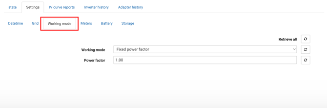
The inverter’s working mode defines how it manages voltage and reactive power to support grid stability. Each mode follows its own control logic, with configurable parameters.
-
No Response Mode - Disables voltage/reactive power control.
When OFF: The inverter actively follows the selected grid code profile and participates in voltage/reactive power support.
-
Volt-Watt – Adjusts active power output based on voltage levels.
-
V1 → Voltage where curve starts.
-
V2 → Second voltage point.
-
V3 → Third voltage point.
-
V4 → Voltage where curve ends.
-
P1–P4 → Active power levels (in % of rated output) at V1–V4.
-
-
V1 and P1 → Typically grid nominal voltage (e.g., 230 V) at 100% power.
-
V4 and P4 → Overvoltage limit where output is reduced to near 0% to protect the grid.
-
Between points, the inverter interpolates smoothly.
-
Example:
-
V1 = 230 V, P1 = 100%
-
V2 = 240 V, P2 = 80%
-
V3 = 245 V, P3 = 40%
-
V4 = 250 V, P4 = 0%
-
-
Volt-Var – Controls reactive power in response to voltage changes.
- V1→ Lower voltage threshold
- V2→ Lower “deadband” limit
- V3→ Upper “deadband” limit
- V4 → Upper voltage threshold
- Max lagging var → Maximum reactive power injection into the grid (positive vars, raises voltage).
- Max leading var → Maximum reactive power absorption from the grid (negative vars, lowers voltage).
- Plock in / Plock out → Hysteresis settings so the inverter doesn’t rapidly switch states when voltage fluctuates near thresholds.
-
Below V1 → Full lagging vars (voltage support).
-
Between V2 & V3 → No reactive power change (deadband).
-
Above V4 → Full leading vars (absorbs vars to lower voltage).
-
Fixed Power Factor – Maintains a constant power factor regardless of grid conditions.
- Power factor value → Range: -1.0 to -0.8 (leading) and 0.8 to 1.0 (lagging).
-
1.0 → Pure active power, no reactive power exchange.
-
< 1.0 lagging (e.g., 0.95 lagging) → Inverter absorbs reactive power from the grid (helps correct low voltages).
-
< 1.0 leading (e.g., -0.95 leading) → Inverter injects reactive power into the grid (helps reduce high voltages).
-
Fixed Reactive Power – Delivers a constant amount of reactive power.
-
Reactive power value (in kVar):
-
Positive kVar → Lagging vars (inject into grid, raise voltage).
-
Negative kVar → Leading vars (absorb from grid, lower voltage).
-
-
Reactive Power = +2 kVar → The inverter constantly injects vars into the grid to help voltage support.
-
Power PF – Manages active power in coordination with power factor.
-
Pb → First active power threshold (% of rated) where PF control begins.
-
Pc → Second active power threshold (% of rated) where PF reaches target.
-
PFc → Target PF at Pc% or higher (positive = lagging, negative = leading).
-
-
≤ Pb% → PF fixed at starting value (often unity).
-
Pb% → Pc% → PF transitions linearly to PFc.
-
≥ Pc% → PF fixed at PFc.
Meter
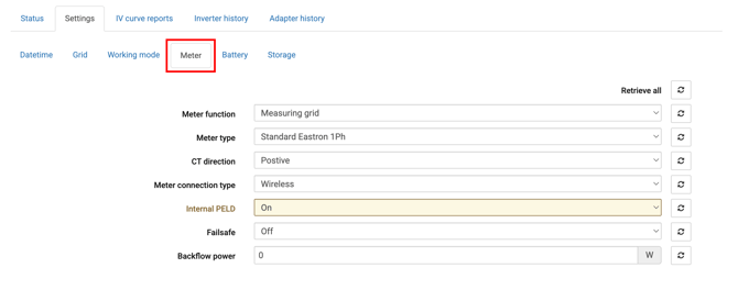
Accurate meter configuration is crucial for optimal solar system performance. In this section, you can define the meter function, type, , and other parameters (depending on the inverter model) to ensure precise energy flow measurement and seamless system coordination.
24h consumption monitoring (only for On-Grid inverters)
Enables continuous 24-hour monitoring of system consumption when a meter is installed.
Meter function (only for Hybrid inverters)
Specifies the meter’s role based on its installation location. Options include:
-
Measuring Grid – Measures energy flow at the grid connection point.
-
Measuring Load – Measures energy flow to the loads.
-
Grid + PV (Two meters) – Measures both grid and PV generation using two separate meters.
Meter Type (only for Hybrid inverters)
Select the exact meter model installed. If the selected type does not match the actual meter, data may be missing or inaccurate.
CT Direction (only for Hybrid inverters)
Defines the CT orientation:
-
Positive – Towards the grid.
-
Reverse – From the grid towards the system.
Meter connection type(only for certain Hybrid inverters)
Specifies how the meter is connected to the inverter:
-
Wired – Direct connection to the inverter.
-
Wireless – Via a wireless device for longer distances.
Internal PELD
-
Failsafe → When enabled, ensures the inverter reverts to a safe default state in case of communication or control failure.
-
Backflow Power – Sets the allowable export power to the utility/grid:
-
For minimum export, set to 0 W.
-
For maximum export, set to the inverter’s output rating.
-
Example: A 3.6 kW inverter → +3600 W
-
Example: A 10 kW inverter → +10000 W
-
-
Battery
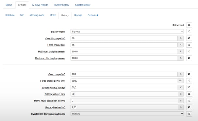
All settings related to your battery can be managed under the Battery tab. Below is a guide to help you understand and configure these settings for optimal battery performance and longevity.
Battery Model
Choose your battery brand from the list. If your system does not have a battery installed, select No Battery.
Over Charge SOC (State of Charge)
This sets the maximum charge level for your battery, between 70% and 100% (default is 100%). It helps protect the battery from overcharging.
Over Discharge SOC
This is the lowest charge level your battery can safely reach, ranging from 10% to 40% (default 20%). The inverter won’t discharge the battery below this to protect it. Note that batteries naturally lose charge over time, so if your battery isn’t charged for a long period, the charge might drop below this limit.
Force Charge SOC
To prevent your battery from going into sleep mode, the inverter will start charging it once the charge drops to this level (default 10%). Charging can come from your solar panels or the grid, if grid charging is enabled.
Force Charge Power Limit
This controls the maximum power used to recharge the battery during forced charging. It can be set between 300W and your inverter’s nominal power, with 500W recommended for most systems.
ATTENTION!
For the health of the battery, it’s important that the battery stays charged, at least above 10%. When OverDischg SOC (20%) is reached, the inverter will stop the battery from supporting the load. The battery will discharge itself very slowly down to the ForceCharge SOC (10%) in a few weeks. When this level is reached and if there is no PV available, a forced charge from the Grid is necessary, this setting must be enabled in the inverter.
To provide a safe and healthy battery operating range, ensure that OverDischg SOC (20%), ForceCharge SOC (10%), Force Charge Limitation (500W), and “Allow charging from grid” from Storage tab have been set.
Maximum Charging Current
Sets the highest current allowed when charging your battery.
Maximum Discharging Current
Sets the highest current allowed when discharging your battery.
Battery Wakeup Voltage
The voltage level that “wakes up” the battery from standby mode.
Battery Wakeup Time
How long the battery waits before fully activating after reaching the wakeup voltage.
MPPT Multi-Peak Scan Interval
How often the inverter scans for the best power points in your solar panels—useful if parts of your panels are shaded.
Battery Healing SOC
A special charge level used during battery maintenance cycles to help calibrate and extend battery life.
Inverter Self-consumption source
A setting to controll if the inverter itself draws power from the grid or from the battery to stay awake. If set to battery it may drain the battery to a low SoC.
Parallel
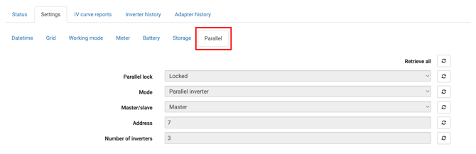
Parallel lock
When you enable synchronization, the datalogger (or system) reads the parallel lock register and copies the master inverter’s parallel parameters to the slave units. Once synchronization completes, the register is set to locked to prevent accidental changes. Always wait for the sync to finish before changing settings.
Mode
Choose Single (standalone) or Parallel operation.
Master/slave
Set each inverter’s role. The master controls operating parameters and aggregates system data; slaves follow the master. The master is also where the system monitoring and meter data are usually connected.
Address
Assign a unique ID to each inverter. The master must be ID 1. Do not use address 0. The valid address range depends on your model, many Autarco hybrid series use IDs from 1 to 6, while some datalogger setups may reference a larger range, always check your model’s manual.
Number of inverters
Set how many inverters are in the parallel string (typical range: 2–6). The system will validate this setting during commissioning.
Storage (only for Hybrid inverters)
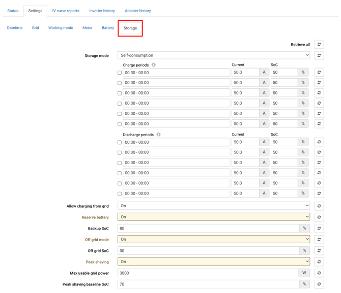
Autarco hybrid inverters offer multiple storage modes to suit different needs, from maximizing self-consumption to trading energy with the grid. This section explains each mode and its settings.
Storage mode
1. Self-Consumption
In this mode, the inverter stores as much generated solar power as possible.
-
Power used by your home is supplied directly from the solar panels.
-
Any excess power is stored in the battery.
-
If no battery is installed, excess power can be exported to the grid (if the system is configured to allow it).
2. Grid Trading
In this mode, the system prioritizes selling electricity to the grid.
-
The battery will only charge or discharge if Grid Trading is enabled and configured.
-
The goal is to maximize energy sales to the grid.
-
The battery is typically used only during short periods or when grid power is unavailable.
Grid trading schedule
This feature lets you set a custom battery charging and discharging schedule based on time-of-day tariffs or personal preferences. There are two versions of Time-of-Use mode, depending on the inverter model.
Version 1
-
Time Charge Current – Sets the maximum charging current during scheduled charge times.
-
Time Discharge Current – Sets the maximum discharging current during scheduled discharge times.
-
Charge and Discharge Times – Define up to 6 specific time periods for charging or discharging (active only when Time-of-Use mode is enabled).
Version 2
-
Each time slot has its own on/off switch, current limit, and target SOC.
-
Allows up to 12 individual time settings for detailed control.
Allow charging from grid
When enabled, the inverter can charge the battery from the grid to maintain a reserve SOC, ensuring backup availability during outages. This setting does not force continuous grid charging, it only charges when needed.
Reserve Battery
When enabled, the system reserves a portion of the battery SOC for emergency backup, only used if the grid fails.
- Backup SoC - Sets the percentage of battery capacity to reserve as backup, adjustable between 10% and 100%, effective only when the Battery Reserve Switch is on.
Off grid mode
The Off Grid mode allows Autarco inverters to operate independently from the utility grid, providing power solely from the solar system and battery storage.
Note that this mode cannot be enabled if the battery’s state of charge (SOC) is below 30%, protecting the battery from deep discharge.
- Off-Grid Overdischarge SOC:
Sets the minimum allowable SOC level during off-grid operation, adjustable between 10% and 100%. This parameter helps prevent excessive battery discharge and extends battery life while off-grid.
Peak shaving
Peak Shaving Mode helps reduce electricity costs by using the battery to supply power during times of high energy demand (peak periods). Instead of drawing expensive electricity from the grid, the system discharges the battery to “shave” the peak. This lowers demand charges and smooths energy consumption.
- Max Usable Grid Power:
Sets the maximum allowable power that can be imported from the grid during peak-shaving, adjustable between 0 and 10,000 W. This limit helps control peak demand at the grid connection point.
- Baseline SOC:
Defines the battery state of charge (SOC) level that must be maintained when the maximum grid import power limit is not reached, adjustable from 10% to 100. When the battery's state of charge (SOC) falls below the baseline level, and the meter power has not yet reached the “Maximum usable grid power”, the system will use the available difference to charge the battery until it reaches the baseline SOC.