Placement and direction of the CT clamps
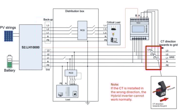
Current transformers (CT) clamps are used by the smart meter to measure the current going from or back to the grid. Considering that the inverter can also measure the current going in and out of the inverter, those two values can be used to calculate the consumption of the load. For this process to be successful, it is crucial that CT clamps are placed precisely. Please see in the image below, what is the correct placement of CT clamps in a PV system.
Keep in mind: the diagram below is relevant for Eastron SDM630MCT meter, added by default to all Autarco 3 phase hybrid inverters. For all other meters, a relevant diagram can be found in the inverter manual.
What happens when the CT clamps are wrongly placed?
If the CT clamps are placed in the wrong spot, the data displayed in MyAutarco will be wrong. Most often this can by realized by looking at the consumption graph. If the consumption is following PV production, or is negative at times, this is an indication that wrongly placed CT clamps might be the issue
Checklist to make sure CT clamps are placed correctly:
- Are all CT clamps measuring correct phases (check meter input vs phase number compatibility on the diagram)
- Are all CT clamps having the arrow pointing towards the grid
- Are the CT clamps placed between the grid connection and the load/inverter split
- Is the setting on the meter setting on the inverter set to "measuring the grid" (this setting can be changed on the inverter's display, in digital O&M in Helios and in the InstallerApp)
Wrong extension of the communication cable between the inverter and the smart meter
For MyAutarco to be able to display the correct data, communication is needed between the smart meter and the inverter. Standard communication cable added in the inverter box is 3m long. Whenever the distance between the inverter and the grid connection is longer than 3m, cable extension is needed.
How to extend the meter cable?
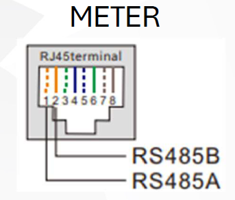
For extending the smart meter cable, wires 1 and 2 off the UTP cable shall be used. The white-orange wire shall be used as RS485A cable whereas the orange cable shall be used for RS485B cable.
Not compatible smart meter was installed
Before installing a smart meter, please check the compatibility table below. Only smart meters included in this list are valid to be used with Autarco inverters.
|
LQH series |
Eastron ESCT-TA16 120A:40mA |
Eastron Meter – SDM630MCT (3*120A:40mA) |
Eastron Meter – SDM630MCT V2 (3*300A:5A) |
Eastron Meter – SDM630-M (100A) |
|
XLH series |
Eastron ESCT-T50-300A/5A |
Eastron Meter – SDM630MCT (3*120A:40mA) |
Eastron Meter – SDM630MCT V2 (3*300A:5A) |
Eastron Meter – SDM630-M (100A) |
|
MH-MIII series |
Eastron Meter – SDM630MCT (3*120A:40mA) |
|
|
Eastron Meter – SDM630-M (100A) |
|
MR-MII series |
Eastron ESCT-TA16-100A/50mA |
Eastron ESCT-TA16 100A/100mA |
Eastron Meter – SDM120CTM (100A:100mA) |
|
|
LH series |
Acrel Meter – ACR10R16DTE4 (3*120A:40mA) |
Eastron Meter – SDM630MCT (3*120A:40mA) |
Eastron Meter – SDM630-M (100A) |
|
|
LH-MII series |
Eastron Meter – SDM630MCT (3*120A:40mA) |
Eastron Meter – SDM630MCT V2 (3*300A:5A) |
Eastron Meter – SDM630-M (100A) |
|
|
MH series |
Acrel Meter – ACR10R16DTE (120A/40mA) |
Acrel Meter – ACR10R16DTE4 (3*120A:40mA) |
Eastron Meter – SDM120CTM (100A:100mA) |
Eastron Meter – SDM630MCT (3*120A:40mA) |
|
MH-MII series |
Acrel Meter – ACR10R16DTE (120A/40mA) |
Acrel Meter – ACR10R16DTE4 (3*120A:40mA) |
Eastron Meter – SDM120CTM (100A:100mA) |
Eastron Meter – SDM630-M (100A) |
|
LD-MII series |
Acrel Meter – DTSD1352 (80A) |
Acrel Meter – DTSD1352 (150A:5A or 300A:5A) |
|
|
|
LD-MIII series |
Acrel Meter – DTSD1352 (80A) |
Acrel Meter – DTSD1352 (150A:5A or 300A:5A) |
Eastron Meter – SDM630MCT (3*120A:40mA) |
Eastron Meter – SDM630-M (100A) |
|
LQ-MII series |
Acrel Meter – DTSD1352 (80A) |
Acrel Meter – DTSD1352 (150A:5A or 300A:5A) |
|
|
|
LQ-MIII series |
Acrel Meter – DTSD1352 (80A) |
Acrel Meter – DTSD1352 (150A:5A or 300A:5A) |
Eastron Meter – SDM630MCT (3*120A:40mA) |
Eastron Meter – SDM630-M (100A) |
|
MX-MII series |
YuanXing CTSA016 -100A/33.33mA |
Acrel Meter – DTSD1352 (60A) |
Acrel Meter – ACR10R16DTE (120A/40mA) |
|
|
MX-MIII series |
YuanXing CTSA016 -100A/33.33mA |
Acrel Meter – DTSD1352 (60A) |
Acrel Meter – ACR10R16DTE (120A/40mA) |
|
|
OX-series |
Acrel Meter – DTSD1352 (150A:5A or 300A:5A) |
|
|
|
|
SX-MII series |
YuanXing CTSA016 -100A/33.33mA |
Acrel Meter – DDSD1352 (60A) |
Acrel Meter – ACR10R16DTE (120A/40mA) |
|
|
SX-MIII series |
YuanXing CTSA016 -100A/33.33mA |
Acrel Meter – DDSD1352 (60A) |
Acrel Meter – ACR10R16DTE (120A/40mA) |
Eastron Meter – SDM120CTM (100A:100mA) |
|
UX-MII series |
Acrel Meter – DTSD1352 (150A:5A or 300A:5A) |
|
|
|
|
UX-series |
|
|
|
|
|
XLX-MII series |
Acrel Meter – DTSD1352 (80A) |
Acrel Meter – DTSD1352 (150A:5A or 300A:5A) |
|
|
|
XLX-MIII series |
Acrel Meter – DTSD1352 (80A) |
Acrel Meter – DTSD1352 (150A:5A or 300A:5A) |
Eastron Meter – SDM630MCT (3*120A:40mA) |
Eastron Meter – SDM630-M (100A) |
|
H-series |
|
|
|
|
|
LX-series |
|
|
|
|
|
MX-series |
|
|
|
|
|
SX-series |
|
|
|
|
|
XLX-series |
|
|
|
|
Connecting the smart meter directly with the EMS instead of the inverter
For use cases where the customer would like to use EMS for steering the system it is important to consider the placement of the meter. In case more generating components are used in a system (for example an AC-coupled cabinet with an on-grid inverter) the meter needs to be connected directly to the EMS controller to ensure suitable control capabilities. Whenever the inverter is steered by an EMS system and the meter is connected directly to the controller it is important to set "no meter" setting, otherwise "meter COM issue" might be reported.
Note: Eastron SDM120MCT or SDM630MCT meter which can be found inside of the Autarco hybrid inverters is also compatible with the Autarco EMS controller.
CT clamps are not compatible to work with the chosen smart meter
Each smart meter equipped with CT clamps has a suitable primary to secondary current ratio. For example, for the Eastron SDM630MCT meter which is added to Autatco 3 phase hybrids, the compatible clamps need to have 120A/40mA ratio. This means that 120A is the maximum measured current for this CT clamp type.
If you are using another smart meter, always check manufacturers installation manual to check, which kind of CT clamps are compatible with the chosen inverter.
Note: For LQH and XLH series, when connecting the inverters in parallel, output current can exceed 120A. Whenever 4 or more LQH inverters are used, or 2 or more XLH inverter, please make sure to use Eastron SDM630MCT v2 meter with 1000A/1A CT clamps